Glued-in threaded rods are among the most powerful connectors in modern timber construction engineering. Whether glued in parallel or perpendicular to the grain direction, powerful forces can be applied in small areas of the wooden components. In conjunction with Professor Ernst Gehri, neue Holzbau AG (n’H) has been conducting research in this area since the late 1990s. Under the brand name “GSA technology”, a range of solutions has since been developed which are being successfully applied in various timber frameworks all over the world.
Wood, resin and steel form an interlocking system, requiring the harmonisation of the three components’ properties. Certain rules and conditions must be complied with if optimum connections are to be created. To avoid any brittle failure modes of either the wood or the adhesive, connections must be designed such that the steel rods (ductile) fail in the ultimate limit state.
This page explains the basics on which the high performances in the GSA design tables are based.
Tender specifications
In construction practice, tender specifications must often strive for product neutrality. The tender specifications for the GSA technology were thus developed according to this principle. Ideally, planners primarily define the required connection forces and the associated dimensions. Since further requirements regarding material, fire safety and humidity may have a significant impact, they are included in the introductory text relating to the respective connections. In addition, the general Terms and conditions can be included in the first section of the specifications.
The Download section contains our entire collection both as an excel file and as an import for the SIA 451 interface. → Example of a simple connection: Truss posts
Requirements
The current standards applying to structural components require framework planners to make various classifications.
Consequence class 1-3 judges the scope of damage when a construction fails. This allows for the deduction of project engineering and implementation parameters. A further aspect consists of the stress type (service category 1-2). In line with common practice in the structural engineering sector, the information provided in this document generally applies to static and quasi-static actions (snow, wind, structural loads in buildings and seismic action, ‘non-ductile’). Cyclical (seismic action, ‘ductile’) and dynamic stresses (fatigue: cranes, live loads, etc.) may also require closer consideration in the planning of glued-in threaded rods. For these applications, steel with special properties may be expedient or even necessary.
Maximum selection of the requirements is not always necessary in the various application modes. Accordingly, the prerequisites associated with a tender in the higher production categories should be more extensive and controls should be more consistent. As regards the production of components with glued-in threaded rods, we therefore suggest the following classification matrix:
| Production Category | Requirements applying to production | Application situations – example |
| PC 1 | low | Reinforcement ⊥ to grain: – lateral pressure in the support – transverse tension in connections and curved components – notches – breakthroughs (dimensioning acc. to standards) Individual rods ‖ to grain: – purlin on posts |
| PC 2 | normal | Small groups (n≤4) ‖ to grain exclusively with normal force: – wall fastenings – high-tensile struts more complex applications ⊥ to grain: – wood-concrete compound – large breakthroughs (ALP) – shear reinforcements |
| PC 3 | high | Group of rods ‖ to grain with normal force and curvature: – Frame corners – bend-proof girder joints and column bases – timber frames |
Performance
Today, materials and even entire frameworks are made to deliver high performance. Since in German, the term ‘performance’ has several meanings, it would be more precise to use the term ‘efficiency factor’ as a measurement of connection performance.
Hence, high-performance constructions distinguish themselves through the fact that they need relatively low material volumes (cross-section area) to meet the applicable requirements. As regards connections, there is always the question by how much they reduce the load resistance or the rigidity of the undisturbed component. The example of a pure tensile splice clearly illustrates this point. The gross area of the cross section times the tensile strength equals the load resistance of the component (100%). This is juxtaposed with the load resistance of the connector group.

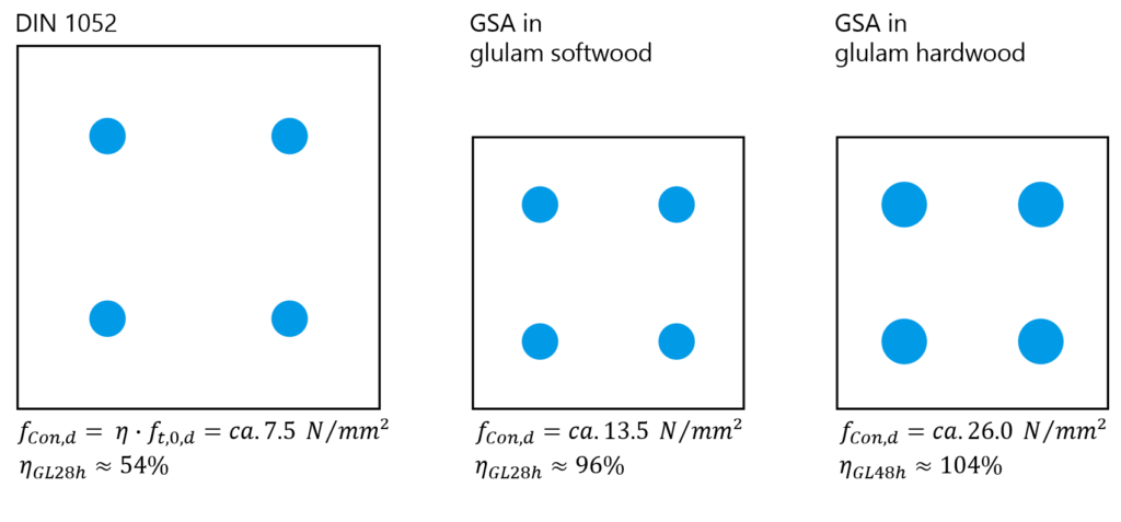
Hence the efficiency factor η can always be calculated from the achieved connection resistance in relation to the respective gross cross section. Most wood connections require some processing that weakens the gross cross section. In the case of glued-in threaded rods, the borehole and any vent holes must be deducted in the calculation of the net cross section. The geometrical conditions of the GSA technology allow for an efficiency factor of approx. 85 %. This weakening in the connection area can be compensated through the local use of superior wood. The following illustration therefore shows ‘impossibly’ high utilisation grades for the stated strength classes. It presents a comparison based on a group of four glued-in threaded rods in horizontal timber. The information relates to humidity class 1. It quickly becomes clear that a tight arrangement of anchors is important to guarantee efficient connection performance. Compared to the approved minimum measurements, larger edge distances and interspaces may sometimes be necessary in real-life construction. Consult our ‘Pre-dimensioning’ chapters in the various GSA applications (for instance: Timber frames).
The stated performance is based on trials
involving representative connections (group of glued-in rods). This was
facilitated by research of the following parameters:
– angle between rod and grain direction
– hole diameter, rod diameter, glue-in length, recess, edge distances and
interspaces
– type of wood, strength class, gross density, wood humidity
– steel quality and profiling
– properties of the adhesive
Compound of wood, resin and steel
The Ph. D theses written by Andrea Bernasconi (1996) and Alessandro Fabris (2001) at ETH Zurich laid an important foundation for the gluing of threaded rods into load-bearing wood components.
They established the concept that force is transferred mechanically between resin and steel as a matter of principle. Suitable bonding resins may have adhesive joints of several millimetres’ thickness. However, it has been pointed out that the type of rod profiling has an important impact on load-carrying capacity. M threads turned out to be perfect for any combination with the current GSA resin. However, subsequent research showed that the resin strength is not a given in higher temperatures (up to 60°C). Consequently, not every resin that works in cold short-term trials is suitable in practical application. If the adhesive is sufficiently powerful, failure occurs in the hole walls (transition from resin to wood). Maximum efficient bonding requires both a very high surface quality of the borehole walls and trained staff to ensure faultless installation.
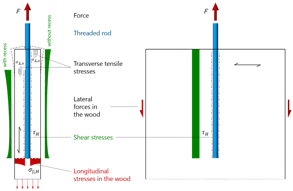
The following model concepts have been
developed on the subject of shear stresses and their course: the course depends
on the ratio between Esteel and Ewood. To keep matters
simple, the resin is assumed to be rigid. The expansions of the resin are thus
consistent with those of the steel. In horizontal timber, the rigidity ratios
lead to stress peaks in the end sections of the adhesive joint. Distortion
(tolerance) results in transverse stresses which have an unfavourable effect on
the wood’s shear strength. This complex stress condition is considered to be
the reason why the load-bearing capacity of a glued-in rod does not increase on
a straight-line basis. Recessing the effective adhesive joint in the component
has a positive effect since this increases the volume of wood that is subject
to transverse tension. The discovery that the hoop tension is a direct function
of the rod diameter is another important finding. Consequently, results from
trials on small rods cannot simply be transferred to larger diameters.
In applications involving crossbars, it may be assumed that shear stresses are
distributed evenly. Thanks to the high rigidity ratio, a longer rod achieves a
higher depth effect.
Parallel or perpendicular to the grain direction
The various types of failure have different levels of importance depending on whether the rods were glued in parallel or perpendicular to the grain direction.
Glued-in threaded rods achieve maximum
effect when their loading is as axial as possible. This document therefore
focuses exclusively on stresses in shaft direction. According to standard SIA
265:2012 (item 6.10.2.1), proof of structural safety is generally to be
provided in respect of:
– failure of the profiled rod
– failure of the adhesive and its bond with the profiled rod and the wood
– failure of the wood along the adhesive joint
– failure of a wooden component in the area of the joint
According to standard SIA 265, the same values may be used for both pressure force and tensile force application. This approach is certainly on the safe side. Tensile stress parallel to the grain thus represents the biggest challenge.
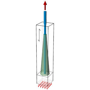
Application parallel to grain: 0° ≤ α < 30°
The state of equilibrium between the force
in the threaded rod and the normal stresses in the cross section of the wood is
achieved via shear stress parallel (II) to the grain direction (II).
The circular cone has a low all-round expansion since the shear module (G) is
much smaller than the E module along the grain direction (E0). From
this consideration, it follows that:
– the ‘activatable area of the wood area’ at the rod end is limited.
– excessive anchor spacing does not improve this.
– many small rods facilitate the optimum distribution of forces.
Proof of the net cross
section of the wood at the end of the rods is always required. In many cases,
the use of higher strength classes is mandatory to support the performance of
the GSA (threaded system anchor).
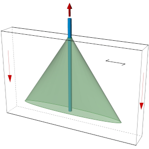
Application perpendicular to grain: 30° ≤ α ≤ 90°
The
state of equilibrium between the force in the threaded rod and the transverse
forces in the cross section of the wood is achieved via shear stress
perpendicular to (⊥) the grain.
Shear stresses have a relatively small spread in the perpendicular direction
(rolling shear). By contrast, a large spread may be assumed in the parallel
direction. The illustration therefore shows an elliptic cone.
In most cases, the length of the rods should be chosen constructively to render
proof in the wood component unnecessary. (For instance, glue-in
length > 0.7*girder depth in the case of transverse connectors
under tension)
Failure of the profiles rod
This mode is pursued to ensure the creation of a robust framework and to keep the dimensioning and model building as simple as possible. In this context, the hierarchy of load resistances must be controlled.

Brittle failure types cannot be excluded unless the anchor guarantees ductility. A ductility factor DS ≥ 3 is facilitated, and these are the only conditions under which the γM/ηM ratio of 1.5 may be applied according to standard SIA 265.
In applications perpendicular to the grain,
the resistance of the wood element is sufficiently high in most cases. This
statement presupposes that the construction takes adequate consideration of the
weak transverse tension properties of the wood. As a rule, this can be achieved
through the right choice of glue-in length.
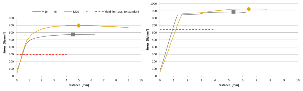
For application as a group in horizontal timber, the exact properties of the
rod material must be determined in advance. The requirements under the product
standards are insufficient to ensure the steel yield limit (upper threshold).
The following illustration shows four exemplary diagrams of individual trials
conducted by the n’H quality assurance unit. The actual yield strengths are
significantly higher than the standard and vary according to diameter. To
ensure that the variance is within the necessary (narrow) range, all rods in
one connection should come from the same production batch.
Wood failure along the adhesive joint
The pull-out resistances in the case of GSA technology are based on a load-carrying model with two fracture criteria. The first describes the shear failure taking the borehole wall as reference area. In addition, compliance with the so-called expansion criterion is required.
In the load-carrying model for shear failure, the numerical value X depends on the wood type and applies exclusively to the defined geometrical ratios. The exponent α allows for the inclusion of the wood direction. Parallel to the grain, it is below 1.0, thus taking account of the non-linear course of the shear stresses.

In his thesis, Fabris has provided a detailed description of model building for the expansion criterion. According to his research, if the rod strength is too high, the rods expand to an extent that wood cannot follow. To determine the characteristic value for spruce, an εu,H of 2.4 ‰ may be used in line with the approval of the German Institute of Construction Engineering (DIBt). As a consequence, only steel types with a low yield limit can be used in parallel applications in spruce. Rods with strengths of 8.8 and above are only expedient for causing brittle failures for research purposes. The following illustration shows a typical brittle fracture with splintering.
Internal trials at n’H prove that rods with a strength of 8.8 are also suitable for practical use in hardwood. The maximum elongations of hardwoods (beech and ash) are sufficiently high.
Generally, this criterion explains why, from a certain point onwards, higher glue-in lengths do not result in higher capacity loads.
GSA technology – characteristics
The design tables show high load resistances at relatively small edge distances and interspaces. To achieve the stated values, both operational expertise and adequate quality assurance are required.
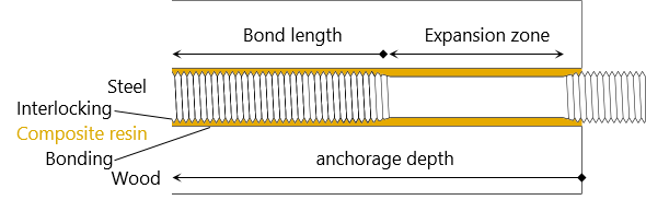
From the beginning, GSA technology was developed with the aim of facilitating efficient anchor spacing. Specific anchor training is therefore part of day-to-day operations. In the respective situations, so-called ‘constriction’ serves the following purposes:
– Since the transfer of force between resin and steel is purely mechanical, the removal of the thread creates an area without adhesive bonding.
– The recessing of the effective adhesive joint increases the volume of wood that is subject to transverse tension.
– Processing to generate the fitting diameter ensures scheduled steel failure and hence ductility.
– After all, the steel is intended to yield exclusively within this defined expansion zone, without destroying the adhesive joint.
In the case of the crucial group applications parallel to the grain, this allows for the linear aggregation of the individual resistances (nef = n1.0). GSA technology thus creates the conditions necessary for straightforward, reliable dimensioning and perfect interaction between wood, resin and steel.
Compressive stress
The stress on glued-in threaded rods caused by pressure is principally less precarious than that caused by tension.
Wood splintering does not become a criterion until the rod threatens to buckle. In a great number of situations, constriction is not necessary. This increases the effective length of the adhesive joint, ensuring the availability of the rod’s entire stress area. In suitable constructions, the contact area of the (face) wood may be considered contributory.
Literature
Further information about glued-in threaded rods in general and GSA-Technology in specific is available in the following publications:
▪ E. Gehri, «Krafteinleitungen mittels Stahlanker» in Brettschichtholz, Weinfelden, 28. SAH-Fortbildungskurs, 1996, pp. 111-143. Order
▪ A. Bernasconi, Tragverhalten von Holz senkrecht zur Faserrichtung mit unterschiedlicher Anordnung der Schub- und Biegearmierung, Publikation 96-3, ETH Zürich, 1996. DOI
▪ E. Gehri, «Klassische Verbindungen neu betrachtet» in HOLZ ART 2000, Luzern, 17. Dreiländer-Holztagung, 2000, pp. 43-50. Order
▪ E. Gehri, «Leistungsfähige Verbindungen: Kriterien und Konzepte» in Verbindungstechnik im Holzbau, Weinfelden, 32. SAH-Fortbildungskurs, 2000, pp. 13-25. Order
▪ A. F. Fabris, Verbesserung der Zugeigenschaften von Bauholz parallel zur Faser mittels Verbund mit profilierten Stahlstangen, Ph.D Thesis ETH Zürich, 2001. DOI
▪ E. Gehri, «Ductile behaviour and group effect of glued-in steel rods» in International RILEM Symposium on Joints in Timber Structures, Stuttgart, RILEM Publications s.a.r.l., 2001, pp. 333-342. Link
▪ R. Steiger, E. Gehri und R. Widman, «Pull-out strength of axially loaded steel rods bonded in glulam parallel to the grain» in Materials and Structures 40, 2006, p. 69–78. DOI
▪ R. Widmann, R. Steiger, E. Gehri, «Pull-out strength of axially loaded steel rods bonded in glulam perpendicular to the grain» in Materials and Structures 40, 2007, p. 827–838. DOI
▪ E. Gehri, «Eingeklebte Anker – Anforderungen und Umsetzungen» in Band I, Prolog IV, Garmisch, 15. Internationales Holzbau-Forum, 2009. Full text
▪ E. Gehri, «High performing jointing technique using glued-in rods» Trentino: World Conference on Timber Engineering, 2010 Full text
▪ G. Tlustochowicz, E. Serrano und R. Steiger, «State-of-the-art review on timber connections with glued-in steel rods» in Materials and Structures 44, 2011, p. 997–1020. DOI
▪ Z-9.1-778, 2K-EP-Klebstoff GSA-Harz und GSA-Härter für das Einkleben von Stahlstäben in Holzbaustoffe, Berlin: Deutsches Institut für Bautechnik, 2012. Downloads
▪ R. Steiger, «In Brettschichtholz eingeklebte Gewindestangen» in Band I, Prolog IV, Garmisch, 18. Internationales Holzbau-Forum, 2012. Full text
▪ R. Steiger, E. Serrano, M. Stepinac, V. Rajčić, C. O’Neill, D. McPolin und R. Widmann, «Reinforcement with glued-in rods» in Reinforcement of Timber Structures, A state-of-the-art report, Shaker Verlag, 2015, pp. 133-159. DOI
▪ E. Gehri, «Verbindungstechniken für auf Laubhölzer basierte Holzwerkstoffe – mit besonderer Berücksichtigung von BSH und LVL aus Buche» in Band I, Prolog IV, Garmisch, 21. Internationales Holzbau-Forum, 2015. Full text
▪ E. Gehri, Performant connections – A must for veneer-based products, Wien: Wold Conference on Timber Engineering, 2016. Full text
If you have any questions, please do not hesitate to contact us. Support